Rubber H07RN-F Submersible Pump Cables Trade Information
Mundra & Nhava Sheva
200000 Meter Per Day
1 Week
Yes
Free samples are available
In a sea worthy wooden reels.
All India
UL, Ce, IS, etc.
Product Description
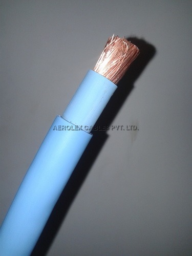
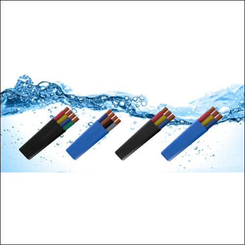
The Rubber H07RN-F Submersible Pump Cables have been specially designed for outdoor utilization purpose. These heavy duty cables are capable of enduring high as well as medium working pressures. These cables are basically used as integral parts of agricultural equipments that have indoor as well as outdoor applications. Featured with weather proof design, these types of cables are completely protected against oil and ozone. The provided cables are designed with thick insulation material, fine strand made copper conductor and rubber core with good insulation level. As an experienced manufacturer and exporter, we are engaged in offering good quality Rubber H07RN-F Submersible Pump Cables.
Key Features:
The provided pump cables are preferred for their excellent electrical conductivity level
These have copper conductor
Long working life and ease of installation are some of their unique features
Easy to maintain
CONSTRUCTION:
Conductor : High immaculateness electrolytic class brilliant tempered adaptable grouped bare, copper conduit as per global guidelines like IS-8130, BS-6360, IEC-228 & VDE-0295.
Insulation : Specially made dielectric class PVC Compound impenetrable to oils, grease, water and so forth.
Sheath : Bendable high friction and inner sheath safe extreme and adaptable PVC Compound.
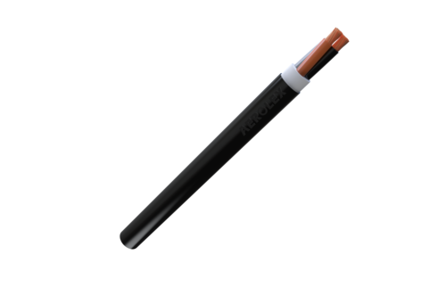
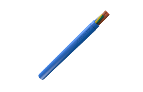
Standard Colors:Grey, Red, Blue, Black, other colors as per requirements.
Application:Use in high ambient temperatures
Standards:IS 694, BS 6500, IEC 60227, CEI 20-20, VDE 0281, SABS 1574, AS 3191, AS/NZS 5000.1, HD 21.1, NF C 32-201, French Standard 32-102-16
Working Voltage Uo/U:450/ 750 V, 600/ 1000 V, 650/1100 V
Test Voltage:3000 V
Temperature range:-150oC to 70oC
3 CORE ROUND
No of conducters in cross-section
no of core x mm2
Mean insulation thickness
mm
Outside diameter min.
mm
Outside diameter max
mm
Max cond. resistance
mm
3 G 1.5
0.8
9.6
12.5
12.1
3 G 2.5
0.9
11.5
14.5
7.41
3 G 4
1
13
16
4.95
3 G 6
1
14.5
20
3.3
3 G 10
1.2
20
25.5
19.1
3 G 16
1.2
22.5
29.5
1.21
3 G 25
1.4
26.5
34
0.78
3 G 35
1.4
29.5
38
0.554
3 G 50
1.6
34.5
44
0.386
3 G 70
1.6
39
49.5
0.272
3 G 95
1.8
44
54
0.206
3 G 120
1.8
47.5
50
0.161
3 G 150
2
52.5
66.5
0.129
3 G 185
2.2
58
71.5
0.106
3 G 240
2.4
65.5
81
0.0801
3 G 300
2.6
72.5
89.5
0.0641
4 CORE ROUND
No of conduct in cross-section
no of core x mm2
Mean insulation thickness
mm
Outside diameter min.
mm
Outside diameter max
mm
Max cond. resistance
mm
4 G 1.5
0.8
10.5
13.5
12.1
4 G 2.5
0.9
12.5
15.5
7.41
4 G 4
1
14.5
18
4.95
4 G 6
1
16.5
22
3.3
4 G 10
1.2
21.5
28
19.1
4 G 16
1.2
24.5
32
1.21
4 G 25
1.4
29.5
37.5
0.78
4 G 35
1.4
33
42
0.554
4 G 50
1.6
38
48.5
0.386
4 G 70
1.6
43
54.5
0.272
4 G 95
1.8
49
60.5
0.206
4 G 120
1.8
53
65.5
0.161
4 G 150
2
58.5
74
0.129
4 G 185
2.2
64.5
79.5
0.106
4 G 240
2.4
73
90
0.0801
Note:
Insulation thickness, Sheath thickness and overall dimensions are nominal values. The number of wires is approximate and strand diameter is nominal; they shall be such as to satisfy the requirements of conductor resistance as per IS 8130
Tell us about your requirement
Price:
Quantity
Select Unit
50
100
200
250
500
1000+
Additional detail
Mobile number
Email
Name
Comapny Name
Phone Number
Email Id
City / State
Confirm Your Requirement
Verification Code
Did not receive yet?
Resend OTP
You’re Done!
We have received your requirements and will reply shortly with the best price.
Products You May Like
Other Products in 'Submersible Pump Cables' category
 Send Inquiry